
Inspection of Multi-diameter Pipelines Operating at Low Pressure
Particularly in the 1940s and 1950s, gas pipeline systems were not necessarily designed and built with inline inspection in mind. As a result, mechanical configurations are encountered that cannot be inspected with currently available inspection equipment. Furthermore, operators are trying to reduce capital and operational expenses by merging different pipeline segments together, resulting in multi-diameter systems. In addition to the challenges presented by the mechanical configuration of these pipelines, the prevailing operating conditions often increase the difficulty of inspecting these pipeline systems.
ROSEN has been working on a variety of projects related to this problem in the past 24 months, and has developed solutions around the following parameters1 :
- Diameter range: 10/12″, 12/16″, 16/20″, 20/26″, 24/30″
- Pipeline length: up to 65 km (40 miles)
- Min. bend radius: 1.5D 90° back-to-back in the smallest diameter
- Wall thickness range: 5.08 mm to 12.70 mm (0.200″ to 0.500″)
- Miter bends: 10 degree – single cut
- Pressure during ILI: 17.24 bar (250 psi)
While the design of an inline inspection system that complies with the mechanical requirements listed above is feasible, if challenging, the low operating pressures in the pipeline systems to be inspected presents an additional hurdle to be overcome. Especially for the utilization of MFL technology in gas pipelines, higher operating pressures are required to achieve constant velocity profiles. When inline inspection of a gas pipeline needs to be executed at low operating pressures, the risk for speed excursions that negatively impact the acquired data is increased. This is a result of the compressibility of the medium in the pipeline. Higher differential pressures are required to move the inline inspection systems through restrictions like bends, diameter transitions and, for smaller diameters, even wall thickness changes. Once the restriction is passed, the differential pressure to move the tools decreases again, allowing the gas to expand. This happens at a rapid velocity, creating a speed excursion.
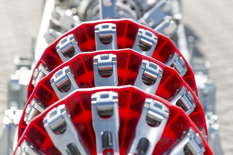
To minimize the extent of speed excursions and therefore improve the data acquisition effort, special characteristics that were previously implemented for single diameter inspection tools are applied to optimize the run behavior of these tools. Furthermore, additional measures need to be taken to optimize the sealing elements in order to achieve the best possible compromise between sealing and the differential pressure required to propel the tool.
In the following paper, an overview will be provided on the general approach for these projects as well as the process related to deploying these new tools in the pipeline industry.